IndustriElectric
Thermocouple, J type, Sheath
Thermocouple, J type, Sheath
Regular price
$137.32 USD
Regular price
Sale price
$137.32 USD
Unit price
per
Couldn't load pickup availability
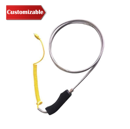
Sheath thermocouple have shielded thermocouple wire of common length 500mm and sheath diameter Ф3~Φ8mm, with flexibility, high pressure resistant, fast thermal response time and long operating life. J type thermocouple can directly measure the temperature of liquid, vapor, gas medium and solid surface in the range of 0~600 ℃ in various production processes, especially in vacuum, oxidation, reduction or inert atmosphere.
As a temperature sensor, thermocouple is usually used with display instruments, recording instruments and signal conditioners. Sheath thermocouple also can be used as a temperature sensing element for assembly thermocouple.
Specification
1. S/E/K/J/T type thermocouple temperature range and accuracy chart
| Category | Type of sensing element | Sheath diameter | Normal working temperature | Highest working temperature | Allowable deviation Δt | |
| Measuring range | Permissible deviation | |||||
| Platinum Rhodium 10 - Platinum | S type | ≥Φ3mm | 1100℃ | 1300℃ | 0~1300℃ | ±2.5℃ or ±0.75%t |
| Nickelchromium - Copper nickel | E type | ≥Φ3mm | 600℃ | 700℃ | 0~700℃ | ±2.5℃ or ±0.75%t |
| Nickel chromium - Nickel silicon | K type | ≥Φ3mm | 800℃ | 950℃ | 0~900℃ | ±2.5℃ or ±0.75%t |
| Iron - constantan | J type | ≥Φ3mm | 500℃ | 600℃ | 0~600℃ | Not specified |
| Copper - Copper nickel | T type | ≥Φ3mm | 350℃ | 400℃ | <-200℃ | Not specified |
| -40~350℃ | ±1.0℃ or ±0.75%t | |||||
2. Thermal response time of thermocouple
| Sheath diameter (mm) |
Thermal response time (s) | |
| Shell type | Insulation type | |
| 2.0 | 0.4 | 0.5 |
| 3.0 | 0.6 | 1.2 |
| 4.0 | 0.8 | 2.5 |
| 5.0 | 1.2 | 4.0 |
| 6.0 | 2.0 | 6.0 |
| 8.0 | 4.0 | 8.0 |
3. Thermocouple wire structure chart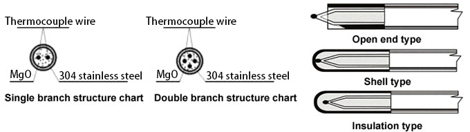
4. Selection chart
| Branch number | Installing form | Mode of connection | Working end form | Multipoint type | Additional device | Sheath diameter | Sheath length |
| B1: Single branch; B2: Double branch |
I1: No fixed device; I2: Fixed card sets of thread joint; I3: Movable card sets of thread joint; I4: Fixed card sets of flange; I5: Movable card sets of flange |
C0: Simple terminals; C3: Standard waterproof protection head; C4: Explosion-proof protection head; C5: Standard plug; C6: Aviation plug; C7: Handheld; C8: Small waterproof protection head; C9: Direct lead wire |
W1: Insulation type; W2: Shell type; W3: Open end type |
M3: 3 points; M4: 4 points; M5: 5 points; M6: 6 points |
S: Sanitary chuck; H: Heat collector |
D3: Φ3; D4: Φ4; D5: Φ5; D6: Φ6; D8: Φ8 |
Φ3: 50~15000mm; Φ4: 50~10000mm; Φ5: 50~4000mm; Φ6: 50~2000mm; Φ8: 50~1000mm |
5. Thermocouple installation diagram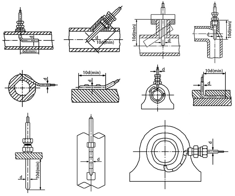
Feature
- High Mechanical Strength: Strong structure with good pressure resistance, suitable for harsh industrial environments.
- Flexible Installation: Can be bent for curved or space-limited mounting scenarios, enhancing installation convenience.
- Wide Measurement Range: Sheath thermocouple suitable for various temperature ranges in industrial and laboratory use.
- Fast Thermal Response: Minimizes dynamic error with rapid response to temperature changes.
- Leak-Proof Insulated Connector: Designed with anti-electric-leakage plastic molding, crafted through multiple precise processes for safety and reliability.
-
Premium Plastic Components: Quality plastic materials offer durability and insulation.
Comfortable Handle Design: Ergonomically shaped grip for safe and easy handling.
Tips: How to prevent interference for thermocouple?
- Isolation
Isolation method is to hang thermocouple in the air to isolate thermocouple from refractory brick of furnace wall, and thermocouple is also isolated from support by use of insulation object. The method can prevent interference of high temperature electric leakage. - Shielding
Shielding method is to make extension wire of thermocouple pass through iron tube or other metal shields to isolate. In this way, it can prevent electromagnetic interference and interference of high voltage electric field. When using this method, iron tube and shields should be connected with the ground well and twist the extension wire as well.
- Ground connection
This method has two forms: The first is to connect the reference end of thermocouple with the ground, and second is to connect the measurement end of thermocouple with the ground.